VueScan - 'Crop' Tab
© Thomas GadeIndex
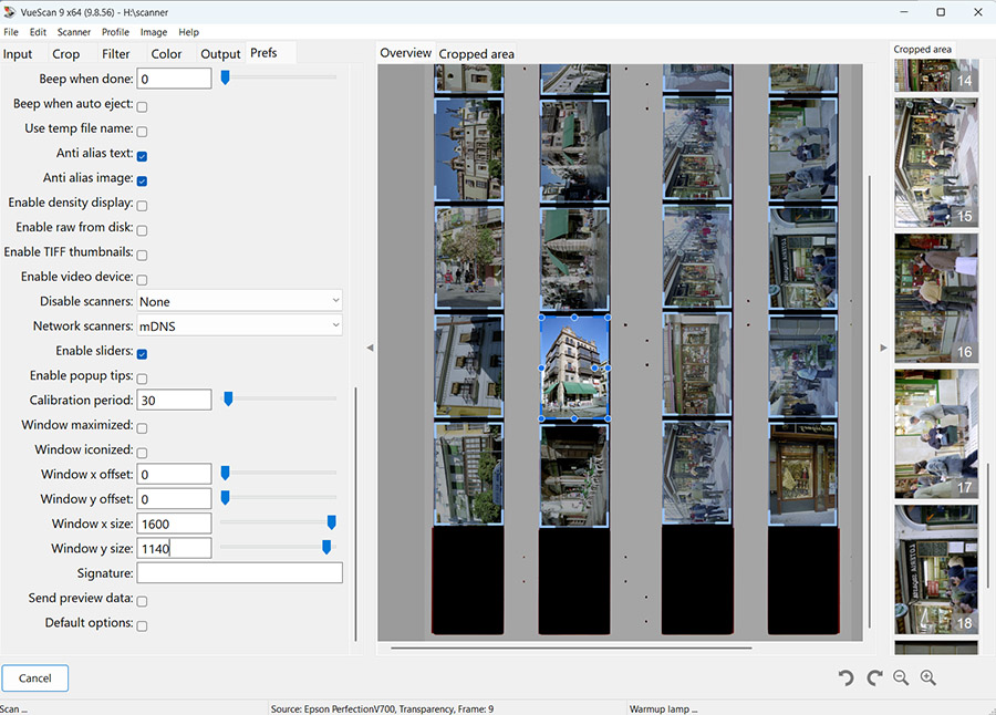
In the 'Crop' tab, you define the settings for the image area to be scanned. However, VueScan now usually detects originals placed on the scan bed of a flatbed scanner automatically. If several originals are found, an additional column appears to the right of the preview window after the 'Preview' has finished, displaying each detected image separately. By clicking on an individual image, you can apply custom settings to that specific scan.
This feature works not only with flatbed scanners but also with film scanners equipped with an integrated film transport mechanism or dedicated film holders.
With most compatible scanners, automatic image detection works as long as the correct setting has been selected under 'Media' in the 'Input' tab. If it does not, some setting in the 'Crop' tab has probably been changed. Under 'Crop Size', select either 'Auto' or the appropriate media type, and set 'Multi Crop' to 'On'. Then start a new 'Preview'. This greatly simplifies the scanning process. If automatic image detection works correctly, no further adjustments in the 'Crop' tab are usually required.
Important: Always make your basic settings before running the preview!
If, as in the example shown above, several film strips with multiple frames are placed on the scan bed, all basic settings should be made before starting the 'Preview'. These include white balance, black and white points, resolution (DPI), file name, destination folder, and the desired options in the 'Filter' tab. These settings will then apply to all detected images. If a particular image requires different settings, simply select it from the column on the right and adjust it individually.
Buffer
One particularly important setting in the 'Crop' tab is 'Buffer (%)'. This determines that only the central area of the image is used for exposure and tonal range analysis, while the image borders are ignored. The resulting corrections are then applied to the entire image. In my experience, a value of 8% has proven to be a good choice.
Why the classic Crop settings are still useful
My earlier, more detailed description of the settings in the 'Crop' tab is therefore by no means obsolete. There are still good reasons to use older versions of VueScan. For example, I use an older laptop running Windows XP (32-bit) to operate a Nikon LS-2000 via a SCSI interface. Since there is no 64-bit-compatible driver for my PCMCIA SCSI adapter, Windows XP provides the required compatibility that newer operating systems no longer offer. On the same computer, I also occasionally use an older Agfa flatbed scanner with a SCSI interface.
VueScan 9.3.22, released in 2013, turned out to be the newest version that still runs reliably under Windows XP. At that time, effective automatic image detection was not yet available. Even with newer hardware, automatic image detection is not always perfect. For example, during my test of the Plustek OpticFilm 135i in 2023, image detection was far from reliable. At that time, Hamrick Software was experimenting with different detection methods, so both the behavior of the automatic image detection and some settings in the 'Crop' tab changed from one update to the next. In such cases, it is still helpful to be familiar with the classic settings in the 'Crop' tab and to use them whenever necessary.

The Crop tab is used to define the scan areas. Example: A film holder containing four film strips is to be scanned automatically.
When scanning individual images, the Crop tab is usually unnecessary because the desired crop area can simply be drawn with the mouse. The tab becomes important when several images are placed on a flatbed scanner and are to be processed automatically. In this case, VueScan needs information about the number of images arranged horizontally and vertically, the spacing between them, and the area of the scanner bed in which they are located. These settings are made in the Crop tab.
Crop Size
Select Manual instead of Auto.
Size X / Y
These values define the dimensions of the crop areas that VueScan creates for each image. The individual crop areas can then be adjusted independently in the preview window by dragging them with the mouse.
Multi Crop
Custom – This setting allows the user to configure all crop parameters manually.
X Images
4 – because four film strips can be placed side by side in the holder. The value remains 4 even if not all positions in the holder are occupied.
Y Images
6 – because each film strip can contain up to six 24 × 36 mm frames. The value remains 6 even if the film strip contains fewer than six frames.
Spacing X / Y
These values define the size of the grid cells in which VueScan expects to find the images to be scanned.
Link X / Y
This setting specifies the distance from the top edge of the scan area to the first row of images. A value of 16 means 16 mm.
Buffer (%)
This setting is very important. If an image is scanned together with part of its border, the border can influence VueScan's interpretation of the scan data. To avoid this, a value of 20% is recommended. This means that VueScan ignores the outer 20% of the crop area when calculating exposure, color balance, and tonal values. The ignored border areas are still scanned and appear correctly in the final image, but they do not affect color interpretation or tonal adjustment. This is roughly comparable to center-weighted metering in photography.
Unlike the standard 24 × 36 mm format, there are also half-frame (24 × 18 mm), Instamatic (24 × 24 mm), and panoramic formats. In these cases, the image dimensions are entered under Size X / Size Y. If a full-length film strip contains eleven half-frame images, enter this value under Y Images. If a full-length film strip contains a maximum of two panoramic images, enter 2 accordingly.
The entire scan area is divided into a grid of individual image fields. For example, if a flatbed scanner is used with a holder for four 35 mm film strips, each containing up to six frames, a 4 × 6 grid is required. This grid is always displayed in the preview window and can be adjusted so that it matches the film holder. Once configured, these settings can and should be saved.
The crop area is important for two reasons. First, it defines the image that will be scanned. Second, VueScan uses this area to calculate color reproduction, tonal distribution, and other image parameters. The border around an image should generally not be included in the crop because it can lead to incorrect calculations. There are, however, situations in which the film border should be scanned as well. Since this border is usually much lighter or darker than the actual image, it should be excluded from the color and tonal calculations. The settings on the Crop tab prevent the border from influencing the exposure and color calculations. If a value of 20% is entered, a narrow, evenly distributed border—up to 20% of the total image area—is ignored during the calculations.
Crop Size
Manual
The crop area is defined manually.
Auto
VueScan analyzes the image and attempts to detect the corners automatically. Whether this works reliably depends on the image and should be tested.
Maximum
The scanner captures the entire scan area. This setting can be useful when VueScan is used to create raw scan files.
The remaining options correspond to various film and print formats.
Size X / Y
The crop size can be adjusted using the sliders or by drawing a frame with the mouse, in which case the dimensions are displayed.
Auto Offset
X / Y Offset

This setting is available when Multi Crop | Custom is enabled. Entering values shifts the starting position of the crop areas within the preview window. VueScan uses X and Y coordinates. On a flatbed scanner, the X-axis runs parallel to the shorter side of the scanner bed.
This setting is of little interest when scanning a single image because the crop can easily be positioned with the mouse. It becomes important when scanning multiple images on a flatbed scanner. See: Batch Scanning
Multi Crop
When Custom is selected, the following X/Y options become available.
The following options are displayed when Multi Crop is set to Custom.
X Images / Y Images
These settings specify how many images are arranged horizontally and vertically on the flatbed scanner. For example, if there are three columns with four images in each column, enter 3 for X Images and 4 for Y Images. The X-axis runs parallel to the short side of the scanner bed, while the Y-axis runs parallel to its long side.
In principle, these settings divide the scan area into a grid. The grid may consist of one or more rows and columns. Every crop area within the grid has the same size, which is determined by the Spacing X / Y settings.
Use this function together with Spacing X / Y.
Spacing X / Y
If more than one image is specified, these settings define the approximate horizontal (Spacing X) and vertical (Spacing Y) distances between the images. For mounted 35 mm slides in standard 5 × 5 cm mounts placed closely together on the scanner glass, both horizontal and vertical spacing should be set to 50 mm. Mounted 6 × 6 cm slides are typically housed in 7 × 7 cm mounts, so the spacing should be set to 70 mm.
Position X / Y
Moves the entire grid to the correct position.
Link X / Y
When this option is enabled, adjusting one crop frame causes all crop frames in the grid to move together horizontally or vertically while maintaining their relative positions.
Show Multi Outline
Turns the display of the multi-image grid on or off.
Auto Rotate
When this option is enabled, VueScan automatically rotates the crop area and positions it so that it captures as much of the image as possible.
Crop Orientation
Portrait or Landscape. The English terms are much clearer than the German translation, which uses less appropriate wording.
Aspect Ratio
If Crop | Aspect Ratio is set to Manual, the aspect ratio between the longer and shorter sides of the crop can be freely defined by the user. For example, if an image is to be printed on 4 × 6 inch paper, the aspect ratio should be 1.5 (6 divided by 4).
Border (%)
This setting instructs VueScan to enlarge the crop beyond its defined edges. This additional border is not included when calculating the image's color balance. The option is useful for compensating for slight errors in the size or position of automatically detected crop areas. If necessary, the images can be cropped accurately later in an image editor.
This option is useful when the borders around an image are scanned but should be excluded from the calculations for tonal values and color correction. A value of 20% is generally recommended when scanning film.
Preview Area
Default should be used unless there is a specific reason to select another option. Crop scans only the selected crop area for the preview. Current uses the size of the previous scan. Maximum scans the entire scan area. Manual provides additional settings.
Position of the Preview Area
These settings determine the position of the area that will be scanned during the preview scan.
For HP PhotoSmart scanners, the Y value should not exceed 190.5 mm. There have been reports of film being scratched when a greater scan length is used.
Focus Offset X / Y
This setting is available only if the scanner supports adjustable focus. It allows you to define the point used for autofocus. The focus point is displayed in the preview window as a small animated square.
Film has a tendency to curl, both lengthwise and across its width. High-resolution scanners usually have only a limited depth of field. If the autofocus is set to the center of the image, the corners may become slightly out of focus because of the film's curvature. To minimize this effect, the autofocus point can be moved from the center toward one side of the film.
Table of Contents:
General
IntroductionCalibration
Scanning black-and-white film
Scanning color negatives
Scanning slides
Identifying film types
Tabs
SourceCrop
Filter
Color
Output
Settings